
A coaxial cable is an electrical transmission line designed to carry high-frequency signals while maintaining a controlled characteristic impedance. It consists of a center conductor, a dielectric insulator, an outer conductive shield, and a protective jacket. This concentric structure helps contain electromagnetic energy and reduce interference when the cable is properly designed and terminated.
Coaxial cables are commonly used in RF communication, antenna systems, video transmission, and automotive electronics. The right cable depends on the system impedance, operating frequency, signal attenuation, connector type, cable length, and installation environment.
For a custom coaxial cable assembly, selecting the cable is only part of the job. Connector compatibility, shield termination, cable routing, and the required electrical tests also affect the performance of the finished assembly.
Common Applications of Coaxial Cable
Coaxial cables are used wherever electrical signals need to travel through a controlled transmission line. The cable specification depends on the signal frequency, system impedance, required signal quality, and installation conditions.
RF Communication and Antenna Systems
Coaxial cables connect radio equipment, antennas, and RF modules. In these applications, characteristic impedance and signal attenuation are important selection factors. Connector compatibility and proper shield termination also matter, especially at higher frequencies.
Video and Broadcast Equipment
Many video and broadcast systems use 75-ohm coaxial cables to transmit video signals. The cable and connectors should match the impedance requirements of the equipment to help minimize signal reflections and maintain signal quality.
Automotive Electronics
Coaxial cable assemblies are used in certain automotive applications, including antenna connections and high-frequency signal paths. Depending on the system design, specialized cable and connector interfaces, such as FAKRA, may be required. The final assembly must also accommodate routing space, vibration, and the vehicle's operating environment.
Industrial and Electronic Equipment
In industrial and electronic equipment, coaxial cables may connect RF modules, measurement instruments, sensors, and communication components. The appropriate cable depends on the electrical requirements and the mechanical constraints of the equipment.
How Does a Coaxial Cable Work?
A coaxial cable carries electrical signals through its center conductor, while the outer conductor provides the return path and acts as an electromagnetic shield. The dielectric material between these conductors helps establish the cable's characteristic impedance.
Unlike an unshielded wire, a coaxial cable has a surrounding conductive shield that helps control electromagnetic interference when the cable and its terminations are properly designed. This makes coaxial construction suitable for many RF and other high-frequency signal applications.
However, shielding alone does not guarantee good signal transmission. Cable geometry, dielectric properties, operating frequency, connector compatibility, and termination quality all affect performance. An incorrectly assembled coaxial cable can introduce impedance discontinuities, signal reflections, or increased signal loss.
Coaxial Cable Structure
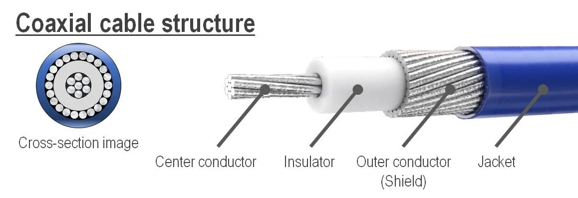
A coaxial cable consists of four main layers: a center conductor, a dielectric insulator, an outer conductor or shield, and an outer jacket. Each layer serves a different purpose, and their dimensions and materials affect the cable's electrical and mechanical performance.
1. Center Conductor
The center conductor carries the signal. Its material, diameter, and construction affect electrical resistance, attenuation, flexibility, and high-frequency performance.
2. Dielectric Insulator
The dielectric separates the center conductor from the outer conductor. Its material and dimensions help determine the cable's characteristic impedance and influence signal loss.
3. Outer Conductor and Shield
The outer conductor provides the signal return path and helps shield the transmission line from external electromagnetic interference. Depending on the cable design, it may use a braid, foil, or a combination of shielding layers.
4. Outer Jacket
The outer jacket protects the cable from abrasion, moisture, chemicals, and other environmental conditions, depending on the selected material. Jacket selection should match the cable's intended installation and operating environment.
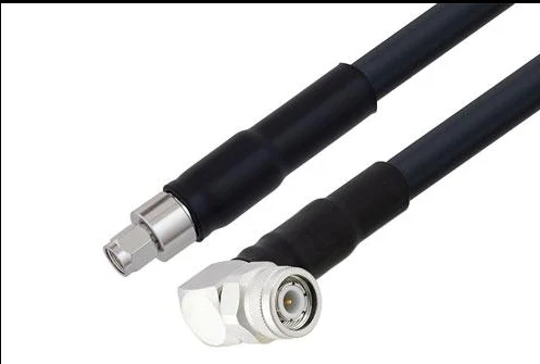
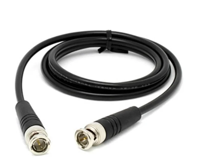
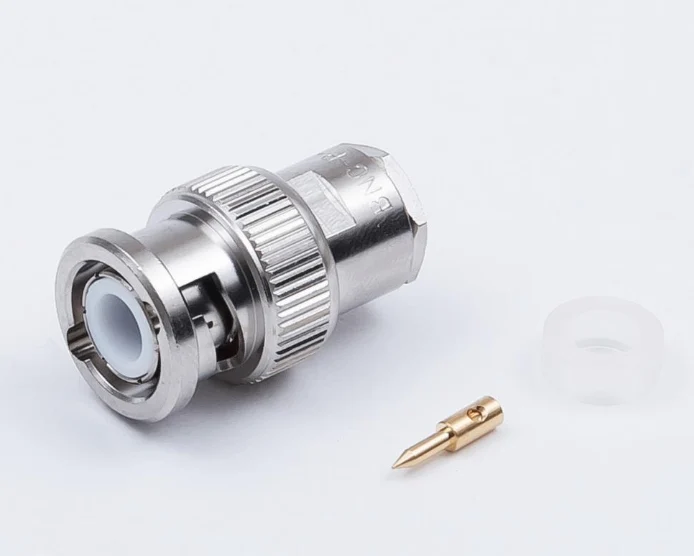
For this reason, shielding termination quality is carefully controlled during coaxial cable assembly manufacturing.
In automotive Fakra cable production, for example, improper shield crimping may directly affect signal stability inside the vehicle communication system.
Common Types of Coaxial Cable
Different coaxial cables are designed for different frequencies, impedance requirements, and installation environments.
| Cable Type | Impedance | Typical Application |
|---|---|---|
| RG58 | 50Ω | RF communication |
| RG59 | 75Ω | CCTV systems |
| RG6 | 75Ω | Satellite & TV |
| RG174 | 50Ω | Compact electronic devices |
| FAKRA Cable Assembly | Depends on the specified system and components | Automotive RF connections |
Coaxial cables are available in different constructions for different electrical and mechanical requirements. The following examples are commonly encountered in RF, video, and electronic equipment applications. Their actual specifications depend on the cable manufacturer and the selected part number.
RG58 Coaxial Cable
RG58 is commonly available as a 50-ohm coaxial cable and is used in various RF, radio, and test-equipment applications. Its relatively small diameter can make routing easier, but attenuation should be checked against the operating frequency and cable length.
RG59 Coaxial Cable
RG59 is commonly available in 75-ohm versions and is used in some video and signal-distribution systems. When selecting it, check the required bandwidth, attenuation, cable length, and connector interface rather than relying on the RG designation alone.
RG6 Coaxial Cable
RG6 is widely used in television, broadband, and other 75-ohm signal-distribution applications. Cable construction varies, so shielding design, conductor type, attenuation, and installation requirements should be confirmed against the intended application.
RG174 Coaxial Cable
RG174 is a small-diameter coaxial cable commonly available in 50-ohm versions. Its compact size can be useful in space-constrained electronic assemblies, but its attenuation may be higher than that of larger cables at the same frequency. Verify the loss over the actual operating range and cable length.
FAKRA Coaxial Cable Assemblies
FAKRA refers to a standardized automotive RF connector interface and coding system, not a coaxial cable type by itself. A FAKRA cable assembly combines a suitable coaxial cable with compatible FAKRA connectors and is used in automotive RF applications such as antenna and selected high-frequency signal connections. Cable impedance, connector coding, frequency requirements, and vehicle installation constraints must all be considered.
50 Ohm vs 75 Ohm Coaxial Cable
The main difference between 50-ohm and 75-ohm coaxial cable is its characteristic impedance. Neither is universally better. The correct choice depends on the impedance requirements of the equipment and transmission system.
| Comparison | 50-Ohm Coaxial Cable | 75-Ohm Coaxial Cable |
|---|---|---|
| Common applications | RF communication, radio equipment, antennas, and test systems | Video transmission, broadcast systems, and television signal distribution |
| Selection priority | Match the RF equipment and system impedance | Match the video or distribution system impedance |
| Key considerations | Operating frequency, attenuation, power requirements, and connector interface | Operating bandwidth, attenuation, cable length, and connector interface |
When selecting a coaxial cable assembly, confirm the specified impedance of the equipment, cable, and connectors. Connecting components with different impedance ratings can create an impedance discontinuity, causing signal reflections. The severity of the effect depends on the mismatch, operating frequency, and overall system design.
For a custom assembly, I would confirm the system impedance first, then check the operating frequency range, allowable attenuation over the required cable length, connector compatibility, and installation constraints. These requirements should be established before choosing a cable part number.
Coaxial Cable vs Twisted Pair Cable
Coaxial cable and twisted-pair cable are designed for different transmission requirements. The better choice depends on the signal type, interface specification, operating frequency, cable length, electromagnetic environment, and installation constraints.
| Comparison | Coaxial Cable | Twisted-Pair Cable |
|---|---|---|
| Construction | A center conductor surrounded by dielectric material and an outer conductor or shield | Two insulated conductors twisted together; additional pairs and shielding may be used |
| Common applications | RF signals, antennas, video, and selected high-frequency connections | Ethernet, differential signaling, control circuits, and many communication systems |
| Signal transmission | Suitable for transmission lines designed around coaxial geometry and specified impedance | Often used with balanced or differential interfaces, depending on the system design |
| Interference control | The outer conductor helps shield the signal path when properly designed and terminated | Twisting helps reduce common-mode noise pickup; shielding may be added where required |
| Selection factors | Impedance, frequency, attenuation, connector type, and routing space | Interface requirements, data rate, cable length, pair configuration, and noise environment |
In practice, I would start with the electrical interface specified by the equipment designer. If the system requires a coaxial RF connection, substituting twisted-pair cable is not a direct replacement. Likewise, a balanced Ethernet or differential signal interface should use a cable that meets its specified transmission requirements.
For custom cable assemblies, the decision should also account for routing space, bend radius, connector availability, strain relief, and the conditions the assembly will face during installation and operation.
How to Choose the Right Coaxial Cable
When selecting a coaxial cable, I would start with the electrical requirements of the equipment rather than choosing a cable based on its appearance or nominal size. The cable must work with the system it connects to, and the complete assembly must also fit the available installation space.
1. Confirm the Required Impedance and Frequency Range
First, confirm whether the system requires 50-ohm, 75-ohm, or another specified impedance. Then check the operating frequency range. These requirements help narrow down suitable cable constructions and connector interfaces.
2. Check Attenuation and Cable Length
Signal loss increases with cable length and generally varies with frequency. Review the cable manufacturer's attenuation data across the required frequency range, using the actual cable length to determine whether the assembly meets the system's signal budget.
3. Match the Connector Interface
Check the connector type, impedance, frequency rating, and termination method required by the equipment. A connector that fits mechanically is not necessarily electrically compatible with the system. For automotive applications, also verify any required connector coding and interface specifications.
4. Review Routing Space and Mechanical Requirements
In compact equipment, I would check the available routing space, minimum bend radius, cable flexibility, and strain relief around each connector. If the cable will move or experience vibration, the assembly design should also account for retention and mechanical loading.
5. Consider the Operating Environment
The jacket and cable construction should suit the actual environment, including temperature, moisture, abrasion, chemical exposure, and any applicable automotive or industrial requirements. These conditions vary by application, so the material should be selected against the project's specifications.
6. Define the Assembly and Test Requirements
Before production, confirm the cable length, connector part numbers, stripping and termination requirements, labeling, and acceptance criteria. Continuity testing is useful for detecting open or short circuits, while applications with defined RF performance requirements may also need specified insertion-loss, return-loss, or other high-frequency tests.
For a custom coaxial cable assembly, I recommend confirming these requirements before finalizing the design. It helps avoid choosing a cable that meets one electrical parameter but does not fit the connector, routing, environmental, or testing requirements of the finished equipment.
For more information on planning a wiring system, see our guide to wire harness design.
How Custom Coaxial Cable Assemblies Are Manufactured
Manufacturing a coaxial cable assembly involves more than cutting a cable to length and attaching connectors. The cable construction, stripping dimensions, shield preparation, and termination method must all match the selected cable and connector specifications.
1. Cable Cutting and Preparation
The cable is cut to the specified length, taking the routing path and connector termination requirements into account. During preparation, care is needed to avoid damaging the center conductor, dielectric, or outer shield.
2. Stripping and Shield Preparation
The jacket, shield, dielectric, and center conductor are prepared according to the connector manufacturer's specified dimensions. Incorrect stripping can leave too little conductor for termination, damage the dielectric, or compromise the shield connection.
3. Connector Termination
The connector is attached using the specified termination method, which may involve crimping, soldering, or another approved process depending on the connector design. The center conductor and outer conductor must be connected correctly to maintain the intended electrical path and mechanical retention.
4. Assembly Inspection
The completed assembly should be checked for cable damage, connector seating, termination quality, and other requirements defined by the drawing or work instruction. Inspection criteria should reflect the selected components and the intended application.
5. Electrical Testing
Continuity and short-circuit checks can identify basic wiring faults. Where the application specifies RF performance limits, additional tests such as insertion loss or return loss may be required using suitable methods and defined acceptance criteria.
For custom cable assembly projects, I recommend confirming the cable part number, connector specifications, finished length, termination method, inspection criteria, and test requirements before production begins. This makes the manufacturing process easier to control and helps ensure the finished assembly matches the customer's application.
For projects requiring broader wiring solutions, explore our custom wire harness design services.
Why Coaxial Cable Is Still Widely Used
Even with the development of newer communication technologies, coaxial cable remains an important solution in many industries because of its:
- Strong EMI resistance
- Stable impedance performance
- Reliable RF transmission
- Long service life
- High-frequency capability
In automotive, industrial, and RF communication systems, coaxial cable assemblies continue to play an essential role in maintaining stable and reliable signal transmission.
Frequently Asked Questions
What is coaxial cable mainly used for?
Coaxial cable is mainly used for RF communication, automotive electronics, CCTV systems, antenna modules, and industrial signal transmission.
What is the difference between RG58 and RG174?
RG58 is thicker and suitable for general RF communication, while RG174 is thinner and more flexible for compact installations.
Why is shielding important in coaxial cable?
Shielding helps prevent electromagnetic interference and improves signal stability.
What connectors are commonly used for coaxial cables?
Common connector types include SMA, Fakra, BNC, MCX, MMCX, and SMB connectors.
Can coaxial cables be customized?
Yes. Coaxial cable assemblies can be customized based on impedance, connector type, cable length, shielding requirements, and application environment.
Conclusion
Coaxial cable remains an important component in RF communication, automotive electronics, industrial equipment, and modern signal transmission systems.
Coaxial cables are designed to provide controlled impedance and shielding for suitable high-frequency applications. Actual performance depends on cable construction, connectors, and termination quality.
As electronic systems continue moving toward higher-frequency communication and smarter connectivity, demand for reliable custom coaxial cable assemblies will continue to grow.


