
[DFM Production Feasibility Analysis (Part 1): From Drawing Review to Material Selection] — in this installment, we completed drawing review and material selection. Now we continue with the manufacturing-side DFM: processes, tooling, quality systems, and self-assessment checklists.
Part 1: Real-World Case Studies
Last June, a rail transit customer submitted a set of wire harness drawings to Kaweei, asking us to assist with a DFM review and concurrently evaluate the estimated production lead time.
The drawings at that time appeared sound: electrical logic was correct, BOM information was complete, and the customer's internal review had been approved and finalized, clearing the way for production. However, after our review, we found that several design aspects, if manufactured exactly as drawn, posed significant manufacturing and reliability risks.
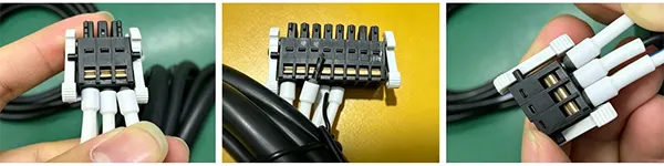
Issue 1: Terminal Insulation Diameter vs. Connector Pitch Not Considered
The original design matched wire gauge to pin terminal size, and the terminals fit the connector cavities. However, the insulation diameter of the pin terminals was relatively wide. When multiple terminals were placed side by side, inserting them into the connector became extremely difficult. Even if forced in, they risked loosening over time. This raises a critical question: do the combined dimensions, tolerances, and assembly clearances still work when multiple terminals are installed simultaneously? This is a frequently overlooked issue in connector, terminal, and wire harness design.
Issue 2: Sleeve Material Not Matched to Environmental Conditions
The original design specified standard PVC sleeving (rated -20°C ~ +85°C) to control costs. Under low-temperature, low-mechanical-stress conditions, standard PVC sleeving would have been perfectly adequate. However, in this project, the harness was routed near heat-generating components, with continuous vibration and potential oil exposure. Under these conditions, material selection based solely on ambient temperature performance is insufficient. Prolonged high temperatures can cause aging and softening, while vibration and oil exposure significantly increase the risk of abrasion and swelling. We therefore recommended re-evaluating material choices based on actual operating conditions, considering PA corrugated tubing, oil-resistant materials, or fluoroplastics depending on temperature, mechanical motion, oil exposure, and environmental media. DFM is not about whether a material can be used — it's about whether it can perform reliably throughout the entire product lifecycle.
Issue 3: Connector Contact Solder Joint Clearance Not Considered for High-Voltage Performance
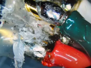
The third issue was found in the connector's internal soldering area. The original design did not adequately account for the insulation distance between adjacent solder joints within the connector.
After soldering, if the effective insulation distance between adjacent joints is insufficient — even if subsequent overmolding with PE or other materials is applied — there is a risk of localized electric field concentration and insulation breakdown during high-potential testing. We recommended adding secondary insulation protection over the solder joint area, and considering silicone or other insulating materials at the joints before overmolding. A seemingly minor dimensional detail can ultimately affect the product's high-voltage performance and production yield.
Part 2: What Exactly Is DFM?
DFM (Production Feasibility Analysis) is not just a check point on the supply chain — it is a systematic engineering approach that asks three fundamental questions from the very first line of design: Can we make it? Can we make it consistently? And will it continue to work reliably over its entire service life? Simply put, DFM is the bridge between the "ideal design" and the "real-world manufacturing."
Why Invest in DFM at the Drawing Stage?
In industrial automation, automotive, robotics, telecommunications, and waterproofing — the five core sectors where custom harness complexity continues to grow — mixed conductor routing, IP68 waterproofing, and frequent bending/flexing requirements all widen the gap between "design feasible" and "manufacturable." This gap has become the primary trigger for project delays, cost overruns, and quality failures in production.
| Stage | Issue Detection Timing | Typical Cost Impact |
|---|---|---|
| DFM Review | Before drawing freeze | BOM/component changes, zero tooling cost |
| NPI Pilot Run | First article validation | Fixture modifications, process adjustments — thousands to tens of thousands |
| Mass Production | Batch defects | Rework, scrap, mold rework — hundreds of thousands and up |
| End Customer | Complaints / recall | Damages, brand erosion, customer relationship repair — incalculable |
Part 3: How Does Kaweei's Engineering Team Conduct a DFM Review?
I. Drawing & Design Assessment
1. Motion Profile Compatibility
First, clarify the harness's actual motion state within the equipment. Generally, this falls into three categories: fixed routing, reciprocating/trailing routing, and bending/flexing routing.
For dynamic applications, key parameters to verify include: minimum bend radius, daily flex cycles, tensile load limits, and vibration frequency.
For high-frequency motion areas such as vehicle cabins, equipment cabinet doors, robot joints, and cable carriers, adequate service loops must be built in to prevent the harness from being under constant tension. At the same time, assembly tolerances must be accommodated with sufficient slack, and clearances checked for friction, pinching, or interference with surrounding structures.
For high-risk motion zones, clear test requirements should be defined at the drawing stage — including temperature cycling, continuous vibration, and repeated bending acceptance criteria.
2. Environmental Compatibility Design
Harness materials and protective structures must match the actual operating environment.
Temperature & Humidity
Differentiate between indoor ambient, outdoor, high-temperature zones, and thermal cycling environments. Wire selection cannot rely solely on conductor temperature ratings; the following factors must also be considered:
- Maximum ambient temperature
- Minimum ambient temperature
- Self-heating of conductors
- Proximity to heat sources
- Long-term temperature rise
- Thermal cycling
For high-humidity, condensation, or water-exposed environments, additional moisture barriers and sealing structures are required to prevent moisture ingress into connectors and the harness interior.
Chemical & Mechanical Environment
If the harness is subject to prolonged exposure to the following, special considerations apply:
Oil, fuel, lubricants: Verify that cable jackets, protective sleeves, seals, and connector materials offer adequate oil resistance to prevent swelling, softening, cracking, or insulation degradation after extended exposure. Where needed, select oil-resistant PVC, TPE, PUR, XLPE or other specialized jacket materials and validate with oil-immersion testing per actual service conditions.
Chemical reagents, acids, alkalis: Evaluate the type, concentration, and temperature of the chemicals involved. Select insulating materials, jackets, and terminal plating with appropriate chemical resistance — e.g., PTFE, FEP, ETFE, PUR, PE. Also avoid direct contact between dissimilar metals to prevent galvanic corrosion, adding protective sleeving, sealing, or surface treatments as needed.
Dust and debris: Focus on sealing at connector mating interfaces and harness junction points. Select connectors with integral seals, cavity plugs, protective caps, etc., and define an IP rating appropriate to the service environment to prevent dust ingress leading to contact failure or insulation breakdown. Examples include silicone seals, EPDM, TPV, PA66 materials.
Salt spray, humidity, coastal environments: Evaluate corrosion resistance of terminals, plating, and shielding layers. Select higher salt-spray-rated platings (e.g., nickel underlayer, tin-nickel alloy) and enhance connector sealing to avoid contact resistance increase or signal anomalies due to corrosion.
Outdoor UV exposure: For locations subject to direct sunlight, select UV-resistant jacket materials to prevent chalking, discoloration, or cracking that compromises mechanical protection and insulation. Examples include UV-resistant PVC, PUR, XLPE, TPU, PVDF.
Continuous abrasion, cable carrier, or mechanical wear: Based on flex frequency, bend radius, and service life requirements, select high-flex, abrasion-resistant materials such as PUR, TPE, nylon braided sleeving, fiberglass braided sleeving, and design appropriate cable retention, bend protection, and strain relief to prevent conductor fatigue fracture.
High vibration and shock: Strengthen harness fixing, anti-loosening, and strain-relief design to prevent terminal disengagement, fatigue at crimp zones, and conductor breakage. Add anti-abrasion sleeving, cable tie points, or shock-absorbing structures as needed.
EMI / Electromagnetic Environment
For control cabinets, vehicle high-voltage areas, and other intense EMI environments, evaluate:
- High shielding demand: High-speed data harnesses (CAN, Ethernet, RS485, etc.), encoders, sensors, feedback signal lines, motor power cables, high-voltage battery systems, electric drive system harnesses, and cables near inverters, motors, and solenoid valves.
- Shielding coverage: General signal lines ≥85%; high EMC applications ≥90%. Material choices: single-layer aluminum foil (general EMI); aluminum foil + tinned copper braid (best overall shielding performance, common in industrial and automotive); copper tape (good flexibility, suited for fixed installations); metal braided sleeving (for applications needing additional abrasion protection).
- Shield termination: For high-frequency signals, 360° circumferential shield termination is recommended (avoid using only a drain wire, which can cause high-frequency leakage). For low-frequency or general industrial applications, a drain-wire connection may be acceptable. For on-board high-voltage systems, the shield must be reliably bonded to the connector housing and equipment chassis. Materials include tinned copper drain wires, copper braided grounding straps, EMC shield clamps, and conductive tapes/fabrics.
- Power and signal routing: Power conductors generate magnetic fields and electromagnetic noise during operation; they must not run parallel to sensitive signal lines over long distances. Separate routing paths, avoid extended parallel runs, and add isolation where necessary. For three-phase AC power conductors, tightly bundled or twisted configurations reduce magnetic emissions. For differential signal pairs, maintain specified twist pitch and impedance requirements.
- Isolation between power and sensitive signals: For high-voltage power, inverter outputs, motor cables, and other strong noise sources, keep adequate safe distance, use independent shielding, avoid sharing protective sleeving with signal lines, and avoid routing signal lines near motors, relays, or solenoid valves. Material suggestions: PA/PET braided sleeving, aluminum foil shielded sleeving, copper braided shielded sleeving, ferrite cores, conductive shielding tapes.
Protective Structure Design
Wire harnesses are rarely installed bare in real equipment, so DFM must also verify that protective structures can be realistically manufactured and assembled.
Wear-prone areas can be protected with abrasion-resistant sleeving or convoluted tubing. Connectors and branch points require special attention to: waterproof sealing, anti-loosening features, latches, strain relief, and cable retention features. Sharp corners and metal openings must be protected so harnesses do not directly contact sharp edges; add grommets or other protection as needed.
Strain Relief Design
The junction between harness and connector is a high-stress concentration area. If the harness bends sharply directly at the connector root, long-term use can cause jacket damage, conductor fatigue, or abnormal terminal stress.
Use flared exits, strain-relief structures, or appropriate fixation to gradually distribute tensile and bending stresses. For longer harnesses, place tie points at intervals to avoid concentrating all loads at the connector root.
Protective Sleeving / Tubing
Sleeve structures must simultaneously satisfy space, bending, protection, assembly, and reliability requirements.
Form selection: Depending on installation space, choose round, flat, or custom-shaped sleeving. For tight spaces, flat configurations may be preferred; for multi-branch areas, integrated split designs can reduce additional splices and potential water ingress points.
Wall thickness: Dynamic flex zones generally require more flexibility, while fixed high-wear areas need more robust mechanical protection.
Assembly fit: Sleeve openings, branch positions, equipment latches, and pass-through holes must all be mutually matched. Define cutting and assembly tolerances clearly to avoid field modifications — i.e., cutting away too much material just to "make it fit," thereby compromising the protective function.
II. Material Alternative Selection
Material evaluation must address not only "is the material available now," but also: can it be consistently supplied in the future? And if substituted, will performance degrade?
1. Supply Chain Risk
For EOL (End-of-Life), long-lead-time, or hard-to-source materials, identify risks early. For example:
- EOL materials: proactively identify qualified alternative part numbers
- Long-lead materials: establish safety stock and develop backup solutions in parallel
- Proprietary or niche materials: prioritize standardized, off-the-shelf alternatives where core performance is not compromised
This reduces project delays caused by single-material supply disruptions during volume production.
2. Pre-Qualification of Alternative Materials
Benchmark alternative materials against original specifications for core parameters: temperature rating, tensile strength, flex life, flammability rating, oil/salt-spray resistance, and shielding effectiveness to ensure no downgrade in service compatibility.
Also evaluate processing adaptation cost, tooling and fixture changes, certification requirements (RoHS, REACH, UL, etc.), and customer-mandated material specifications.
3. Connectors & Associated Components
For connector replacements, pay special attention to: overall dimensions, pin-out definition, locking/latching mechanisms, mating force, terminal specifications, electrical performance, IP rating, and assembly compatibility.
Connectors that "look the same" externally are not necessarily interchangeable.
4. Validation of Alternative Materials
Alternative materials should not be switched directly from supplier qualification to volume production.
We recommend a phased approach: pilot batch → application validation → assembly validation → performance testing → production transition. Maintain traceability records comparing old and new materials, and update drawings, BOMs, and part numbers accordingly.
Next installment preview: We will cover process selection, tooling and fixture design, and the APQP quality assurance framework — [DFM Production Feasibility Analysis (Part 2): Process Selection, Tooling Design & APQP Quality Assurance]


