
Previous review: [DFM Production Feasibility Analysis (Part 1): From Drawing Review to Material Selection] we completed drawing review and material selection. This part continues with the manufacturing-side DFM: processes, tooling, quality systems, and self-assessment tools.
3. Process Evaluation
Different harness structures require different manufacturing processes. The core of DFM is not choosing the "most advanced process" but selecting the process that matches the product structure, materials, and application environment.
| Application Requirement | Recommended Process | Reason and Advantages | Design Evaluation Focus |
| General electrical connections requiring stable reliability and suitable for mass production | Terminal Crimping | The most mature harness connection method, forming stable electrical connection through mechanical compression of terminal and conductor; high production efficiency, controllable cost, easy maintenance and replacement | Terminal-to-wire matching, crimp height (CCH) control, conductor fill ratio, pull-off force and cross-section analysis verification |
| Multiple conductor joining, large cross-section connections requiring low resistance and high reliability | Ultrasonic Welding | Achieves metallic molecular bonding through high-frequency vibration, eliminating traditional terminals, reducing connection resistance and saving space; suitable for high-current, high-vibration environments | Conductor material compatibility, welding energy, amplitude, pressure parameters, weld zone dimensions, contact resistance and mechanical strength verification |
| High-current, high-load connections requiring long-term stable conductivity | Resistance Welding / Thermal Welding | Forms permanent connection through localized heat, reducing contact interfaces and improving current-carrying capacity and long-term reliability | Welding current and time control, heat-affected zone control, temperature rise testing, cycle life verification |
| Connections requiring waterproof, dustproof and pull-out protection | Low Pressure Molding | Uses low-pressure hot-melt material to encapsulate the connection area, enhancing sealing and mechanical strength while protecting internal structure | Material flow properties, material compatibility, overmold thickness, gate and vent design, sealing reliability verification |
| Long-term water exposure, high humidity, high IP rating requirements | Potting / Coating | Fills internal spaces with sealing material to form an integral protective barrier, improving waterproof, moisture-proof and corrosion resistance | Material shrinkage, curing stress, thermal expansion matching, compatibility between potting material and harness materials |
| Space-constrained, lightweight and compact design required | Connection Structure Optimization | Reduces size and weight through optimized connection methods, materials and routing, improving installation convenience | Wire gauge optimization, connector selection, routing layout, assembly space analysis |
4. Tooling and Fixtures
Tooling and fixtures are often overlooked in DFM but directly affect mass production efficiency. Before formal production, confirm the following:
| Tooling (Molds) | Fixtures |
| Does the crimping die match the terminal specification? Is the injection mold structure suitable for product demolding? Does the mold require sliders, inserts, or other complex structures? Does the mold life meet the expected production volume? Are later changeover and maintenance costs acceptable? | Crimping positioning fixtures; welding fixtures; injection molding positioning fixtures; assembly fixtures; testing fixtures; error-proofing fixtures |
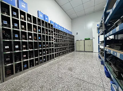
Once mold requirements and design are confirmed, how long does it take from mold design to production? This depends on the specific product structure and mold complexity; it is recommended to confirm lead time with the mold supplier during the DFM review phase.
Part 4: Process Assurance
For DFM to be effective, a report alone is far from enough. It needs to be embedded in a rigorous engineering quality management system and validated with physical samples. We embed the review into the automotive industry APQP methodology framework, forming a three-tier connection.
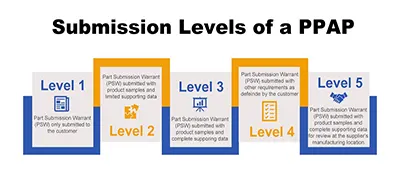
4.2 Seamless NPI Integration, 24–72-Hour Validation
No matter how perfect the DFM paper conclusions are, they must be verified by physical samples. Kaweei's independent NPI (New Product Introduction) process quickly takes over, completing first-article physical validation within 24–72 hours, turning design-phase judgments into tangible, testable, and deliverable samples.
Part 5: Tool Kit — Quick Self-Assessment Checklist for Wire Harness DFM
Before entering a formal DFM review, you can use the following checklist for a quick self-check to screen out some common issues:
Cables and Conductors
- Conductor type: Stranded/solid/flexible conductor selected? For applications such as drag chains, robotic joints, or rotary tables, prioritize more flexible/stranded conductors. For fixed wiring inside control cabinets, prioritize solid conductors with higher stability and rigidity.
- Conductor material: Bare copper/tin-plated copper (general environments), silver-plated copper (high temperature ≥200°C, high-frequency signal transmission, low loss), nickel-plated copper (extreme high temperature ≥250°C, good stability), copper alloy (cost-sensitive, weight reduction, RF/coaxial cables).
- Flexible bending radius standards: Static installation ≥6–10× cable OD (standard cables), high-flex cables ≥4–5× OD; dynamic bending ≥10–15× cable OD (standard flexible cables), high-flex drag chain cables ≥7.5–10× OD.
- Insulation material: PVC / XLPE / Teflon (PTFE/FEP/PFA) / TPU / LSZH / Silicone — does it match the rated temperature, voltage rating, flame retardant requirements (e.g., UL94 V-0), and chemical environment compatibility?
- Temperature rating covers maximum operating temperature: Choose appropriate temperature rating based on installation location, distance from heat sources, and ambient temperature. Typical engine compartment areas require –40°C to +125°C; areas near heat sources require –40°C to +150°C; extreme high-temperature areas such as exhaust manifolds and turbochargers require ≥200°C high-temperature wire and protective structures.
- Are cable certifications complete? UL, flame retardant (UL 1581 VW-1/FT-1), RoHS/REACH, CE, VDE, etc.
Terminals and Connectors
- Terminal wire range match: Check the wire size range compatible with the terminal specification.
- Does the terminal have a corresponding crimping die: For non-standard terminals, confirm die availability and lead time.
- Connector position count and keying features marked: Pin positions, color coding, secondary locking (CPA/TPA) requirements noted.
- For vibration environments, choose terminals with anti-vibration features: Terminals with retention features (e.g., TPA/secondary lock) and connectors with latching/click-lock mechanisms; for automotive vibration scenarios, prefer terminals/connectors that meet USCAR standards.
- Calculate current-carrying margin for high-current circuits: Match terminal temperature rise with wire current-carrying capacity.
- Shield termination method: For high EMC requirements, prefer 360° circumferential crimping (shield ring/clip); "cut-and-shrink" (pigtail) method is not recommended for high-frequency/high-EMC scenarios, but may be used for low-frequency or non-critical signals.
- Check mating cycle life: Number of mating cycles for service interfaces should meet the product lifecycle.
Structure and Assembly
- Branch positions and length tolerances are reasonable: Avoid branch points in bending zones; length tolerances must be within process capability (e.g., for a 10m finished length, tolerance at least 20mm); provide transition protection at branches.
- Strain relief for multi-conductor harnesses: Inner conductors must not be flush; the center conductor should be shortest, and outer conductors progressively longer to form a stepped length difference, so that each conductor bears even stress when bent, preventing outer conductors from breaking and inner conductors from bunching.
- Waterproof seal compression ratio: Seal compression ratio 15%–30% (for rubber parts); verify both ends — compression ratio at both wire end and housing end must be within specification; compression ratio = (original cross-section diameter – compressed height) / original diameter × 100%.
- Labeling scheme defined: Label position readable; printing method or label material meets abrasion/scratch/temperature resistance; content includes traceability information; label thickness does not affect assembly.
- Assembly sequence feasible: All sequential parts have been checked — are any parts that must be "pre-threaded before crimping" (waterproof plugs, seals, boots, heat-shrink tubing, shield rings, etc.) missing? (This is one of the most common low-level errors in reviews). Simulate the assembly process to ensure every step is installable.
- Serviceability considered: Connectors can be mated/unmated by hand or tools; clear identification for installation/removal.
Testing and Supply Chain
- Test requirements specified: 100% continuity test, withstand voltage value, insulation resistance value, pull-out force requirements, etc.
- Critical material lead times: For long-lead items (>8 weeks), initiate alternative evaluation.
- EOL risk checked: No obsolescence warnings for connectors, cables, or other materials.
- Environmental compliance confirmed: RoHS / REACH / halogen-free compliance certificates.
Part 6: Conclusion — The Best Time for DFM Is Before the Drawing Is Finalized
Why can a perfect drawing not always produce a perfect harness? Because the drawing defines "what it should be," while DFM addresses "how to build it in the real world and whether it will hold up."
In the field of custom industrial wire harnesses, Kaweei does not position itself as a "contract manufacturer" — we are a Full-Stack Engineering & Adaptability partner, deeply covering five core areas: industrial automation, automotive, robotics, communications, and waterproofing.
We do not just build to print; we participate from the drawing stage, using DFM to help customers get the design right.
We do not just provide harness products; we provide end-to-end engineering capabilities from material solutions, process selection, tooling design to NPI validation.
Our DFM is not a one-time review service, but a continuous engineering output based on APQP/PPAP systems, DFMEA/PFMEA methodologies, and thousands of mass-production projects across dozens of industries.


