
Why is 100% Testing Critical for Custom Wire Harnesses?
Custom wire harnesses are often used in critical applications such as automotive safety systems, medical devices, and industrial robots. An undetected open circuit, short circuit, or insulation defect can lead to equipment downtime, safety failures, or even personal injury. For complex harnesses with multiple branches, multiple connectors, and mixed signal types, sampling inspection cannot cover all potential risk points—only 100% individual inspection ensures that every harness delivered meets the design requirements.
Kaweei embeds 100% electrical testing into the complete manufacturing chain from development to mass production, covering three major phases: development validation, in-process & end-of-line testing, and reliability testing.
I. Development Phase Testing (Design Validation)
Before a product enters mass production, the first round of electrical validation begins during the DFM review phase, ensuring the design itself is manufacturable and testable.
1.1 First Article Validation Testing
l Continuity Test: Verifies connectivity of all conductive paths, detecting wrong wires, missing wires, and shorts.
l Insulation Resistance Test: Applies test voltage based on different harness types to measure insulation resistance between conductors, and between conductors and shields/exposed conductive parts, assessing the reliability of insulating materials and assembly processes.
l Hi‑Pot / Dielectric Withstand Test:
Two testing strategies are distinguished based on the harness rated operating voltage, with leakage current monitored throughout:
(1) Low-voltage harnesses (≤60V DC / ≤30V AC): DC withstand voltage testing is used, typically 500V DC ~ 1000V DC (per customer specifications), applied for 1–60 seconds. DC leakage current is monitored simultaneously, with a typical threshold ≤1–5 mA, verifying insulation integrity of low-voltage circuits under overvoltage conditions.
(2) Medium- and high-voltage harnesses (>60V DC / >30V AC, including new energy vehicle high-voltage harnesses, industrial equipment power harnesses, etc.): A dual‑mode verification strategy with AC Hipot as primary and DC Hipot as supplementary is adopted. AC test voltage is set at 2× rated operating voltage + 1000V (e.g., 400V system → AC 1800V), applied for 1–60 seconds, with AC leakage current monitored (threshold typically ≤0.5–5 mA, adjusted based on harness length and insulating material);
1.2 Crimp Quality Validation
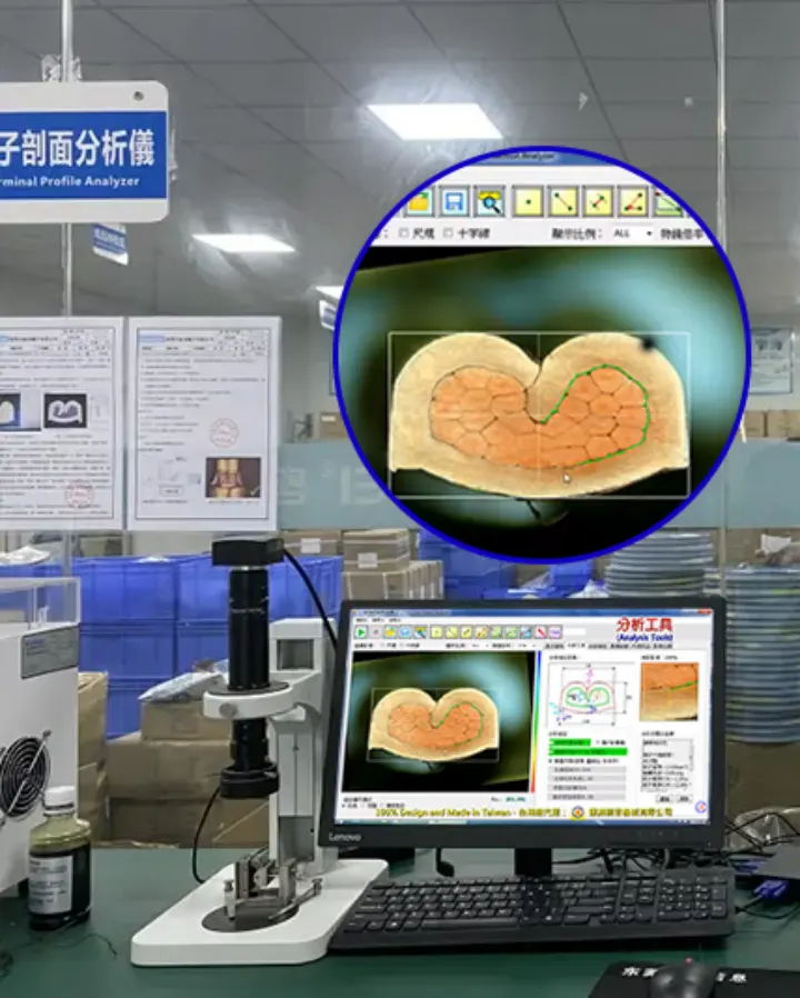
In the first article phase, cross‑section analysis is performed on crimped terminals to inspect critical characteristics including crimp height (CCH), crimp width (CCW), conductor fill ratio, terminal deformation, and conductor crimp zone integrity, confirming that the crimp structure meets terminal manufacturer specifications and applicable standards such as IPC/WHMA‑A‑620 Class 2 or Class 3.
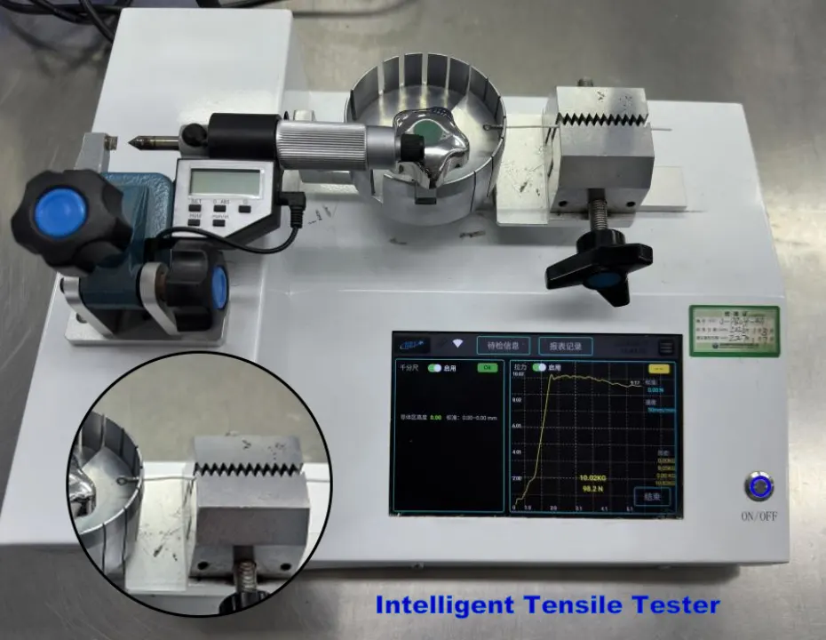
Additionally, crimp pull‑force testing measures the mechanical joint strength for each terminal and wire type, confirming that the mechanical retention force of the crimped connection meets corresponding requirements. Test data is correlated with terminal model, wire gauge, crimp die number, and process parameters, forming traceable process data and serving as the basis for SPC process monitoring and anomaly determination in mass production.
II. Mass Production Phase Testing (In‑Process + End‑of‑Line)
Once in mass production, the testing strategy is divided into in‑process testing and end‑of‑line inspection, achieving full‑chain coverage.
2.1 In‑Process Testing
After each critical process step, in‑process inspection is performed to trap defects within that operation. The table below shows the test items and inspection methods for each step:
Process | Test Item | Test Equipment / Method | Sampling Frequency |
Cutting & Stripping | Wire length, strip length, wire gauge | In‑line inspection by automatic wire processing machine | First article + every 2 hours |
Terminal Crimping | Crimp height & width, cross‑section analysis, pull‑force | Digital micrometer, pull‑force tester, terminal cross‑section analyzer | First article + every 2 hours |
Soldering / Ultrasonic Welding | Joint strength, contact resistance | Micro‑ohmmeter + microscopic inspection, Hi‑Pot test | First article + scheduled sampling |
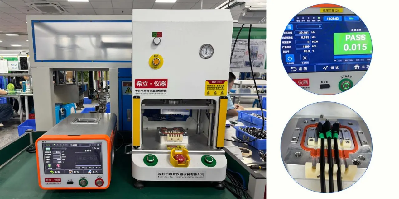
Overmolding / Potting | Visual defects, dimensions, insulation | Visual inspection, insulation resistance test, air leakage test | First article + scheduled patrol |
Assembly | Connector insertion force, latch confirmation | Fixture‑assisted inspection + manual confirmation | 100% individual check |
All in‑process test data above is entered into the MES system; any anomaly immediately triggers a production line stop for investigation, ensuring issues do not flow to the next operation.
2.2 End‑of‑Line Testing and Shipment Validation
After harness assembly is completed, the final electrical and functional validation phase begins. Kaweei establishes an end‑of‑line test plan based on the product's electrical architecture, rated voltage, protection rating, application environment, and customer requirements. Every fully assembled harness must pass the following 100% electrical tests before release.
Basic Electrical Tests:
l Continuity / Wire Mapping Test: Point‑by‑point verification of each circuit in the harness, confirming wire connections, routing, and terminal status.
l Insulation Resistance Test: Verifies insulation performance between conductors and, where applicable, between conductors and shields or exposed conductive parts.
l Hi‑Pot Test (when applicable): AC/DC Hi‑Pot per specific harness specifications.
Specialized Functional Tests (selectable by product type):
l Air Leakage Test: Verifies sealing performance of waterproof connectors.
l Intermittent Fault Detection: Dynamic continuity during flexing.
l Shield Continuity Test: Verifies electrical continuity between shield and ground.
l Other Functional Tests: Depending on the product's actual functionality, additional tests can be configured for polarity, low resistance, sensor signals, communication, and customer‑specific functions.
2.3 Test Data Traceability
All test data is recorded in real time through the MES system, and test records can be linked to:
l Product model and version;
l Work order / batch number;
l Test program and program version;
l Test equipment and equipment ID;
l Test time;
l Operator;
l Key test parameters;
l Test results and anomaly records.
For non‑conforming products, the system performs anomaly result recording and quarantine management, preventing products that have not been re‑evaluated or confirmed as reworked from directly entering the shipping process. By correlating test data with production information, full traceability from product → batch → test program → test results is achieved, providing a data foundation for quality analysis, anomaly investigation, and continuous improvement.
2.4 Testing and Failure Risk Control
By clearly defining the detection capability and applicable boundaries of each test, combined with first‑article validation, in‑process monitoring, and production sampling, comprehensive quality control is achieved from product development to mass production.
Test Item | Test Method | Detectable Failure Modes | Common Blind Spots | Kaweei Solution |
Continuity | 100% point‑to‑point testing, automatic routing and continuity comparison; | Wrong wires, missing wires, shorts, opens, terminals not crimped or fully inserted, wiring errors | Static continuity testing may not detect intermittent opens during vibration, flexing, or movement | For dynamic applications or high‑reliability projects, add dynamic flex, bend, or motion continuity validation |
Insulation Resistance | Test voltage set per product rated voltage and customer specifications; insulation resistance pass/fail criteria set per product specifications | Damaged insulation, moisture, contamination, foreign object bridging, abnormal leakage between terminals | Passing insulation resistance ≠ insulation is risk‑free, as this test has limited resolution for localized micro‑defects (internal voids, pinholes, localized carbonization), early microscopic aging, or breakdown risks that only manifest under high electric field stress. | Adopt a combined test strategy: insulation resistance screening → Hi‑Pot testing for evaluation → partial discharge / dielectric loss analysis for critical components. |
Hi‑Pot | AC or DC test voltage, ramp time, hold time, and leakage current limits determined per rated voltage and product standards | Micro‑cracks in insulation, weak points, insufficient creepage / clearance, insulation failure from molding or potting defects | Testing only between individual conductor and ground misses conductor‑to‑conductor faults. Common insulation defects (such as crimp copper debris piercing insulation, damaged insulation touching other wires, solder points too close) are not detected by ground‑referenced tests. | For multi‑conductor products, both tests must be covered: each conductor to shield / ground, and between each pair of conductors; |
Terminal Pull‑Force & Crimp Section Analysis | Pull‑force limits set per terminal, wire gauge, and supplier specifications; cross‑section inspection checks CCH, CCW, conductor fill state, conductor and terminal crimp zone integrity; | Under‑crimp, pseudo‑crimp, abnormal crimp deformation, conductor damage, abnormal conductor fill, and other internal defects | Destructive validation, typically not feasible for every product; single first‑article analysis does not represent the entire production run. | Cross‑section inspection must be done at first production run, upon crimp die change, or wire change. Link cross‑section results with crimp parameters and die number to provide a baseline for subsequent mass production. |
Air Leakage | Positive or negative pressure decay method based on product sealing structure; test pressure, stabilization time, test time, and allowable leakage set per sealing structure and requirements | Insufficient O‑ring compression, seal plug anomalies, overmolding defects, housing seal issues, joint area leakage, etc. | Air leakage test primarily validates leak performance of the sealing structure, not directly equivalent to IP67/IP68 ratings; different structures require different test pressures and leakage criteria. | Customize the air leakage test plan and thresholds according to product structure; for IP67/IP68 projects, combine with actual immersion time/depth rating verification and perform real immersion environment simulation testing. |
Temperature Rise | Continuous current‑carrying test per product rated current and actual operating conditions, monitoring temperature rise at terminals, contacts, and conductors | Excessive crimp resistance, poor terminal contact, insufficient conductor cross‑section, localized heating at connection points | Harness heating includes both conductor self‑heating and terminal contact heating; attributing excessive temperature rise solely to wire gauge ignores terminal contact issues. | Multi‑point temperature measurement to locate hot spots: measure temperature at conductor body, crimp zone, and mating face separately; if rise is significantly higher than conductor body, prioritize investigation of crimp process, contact resistance, and terminal fit.
|
III. Reliability Validation Testing
In addition to daily production testing, Kaweei's laboratory offers the following reliability testing services for demanding automotive, industrial, and military applications.
3.1 Environmental Reliability Testing
3.1.1 Constant Temperature & Humidity Testing
What it is — Continuous exposure of harness samples in a controlled temperature and humidity chamber to observe the stability of mechanical and electrical properties of insulating materials, cable jackets, connectors, rubber seals, and metal terminals under long‑term temperature and humidity stress, assessing material aging trends.
Why perform it? Harnesses in engine compartments, outdoor automation equipment, industrial control cabinets, and some medical devices may face temperature/humidity variations or prolonged high‑humidity environments. High temperature and humidity can cause moisture absorption, leading to risks of insulation resistance degradation, corrosion of metal terminals, changes in seal properties, and deterioration of plastic mechanical properties, potentially resulting in connector contact failure.
Kaweei is equipped with a programmable constant temperature and humidity chamber, with temperature range ‑70°C ~ +150°C and humidity range 10% ~ 98% R.H., meeting IEC 60068‑2 humidity testing standards. It supports constant humidity, cyclic humidity, and combined temperature‑humidity cycle test modes, with the ability to customize profiles per customer specifications.
3.1.2 Thermal Shock Testing
What it is — Rapid transfer of harness samples between hot and cold chambers, subjecting the product to severe temperature changes. Thermal shock testing focuses not only on peak temperatures but also on the thermomechanical stress induced by rapid temperature transitions.
Why perform it? Harness assemblies contain multiple materials: copper conductors, metal terminals, plastic connectors, rubber seals, potting compounds. Each material has a different coefficient of thermal expansion. Under rapid temperature cycling, the expansion and contraction rates of various components differ, accumulating stress at joints. Long‑term cycling may cause material micro‑cracks, seal gaps, crimp/solder joint thermal fatigue, and potting cracking, directly compromising connector sealing and causing contact failures.
Kaweei is equipped with a two‑zone thermal shock chamber, with shock temperature range ‑55°C ~ +150°C, zone transfer ≤10 seconds, and recovery time 3~5 minutes. Meets GB/T 2423.22 thermal shock test standards.
Test | Primary Simulation | Key Findings |
Constant Temp & Humidity | Prolonged high temperature & humidity | Moisture absorption, aging, insulation degradation, corrosion |
Thermal Shock | Rapid temperature changes | Thermal expansion/contraction, material stress, seal failure, thermal fatigue |
3.1.3 Salt Spray Testing (NSS / AASS / CASS)
Using a salt spray chamber to simulate a corrosive salt‑laden humid atmosphere, assessing the corrosion resistance of harness metal components. C1‑C5 are corrosion environment classifications defined in ISO 12944; NSS (neutral salt spray), AASS (acetic acid salt spray), and CASS (copper‑accelerated acetic acid salt spray) are salt spray test methods.
In salt‑laden, humid environments, terminal platings and connector metal shells can corrode. Corrosion damages plating and causes contact resistance drift, potentially leading to signal interruption and connection failure. Salt spray testing is not just about observing whether samples rust; it validates whether the connector system's mechanical retention and electrical connection can maintain design requirements under corrosive environments.
Corrosion Level | Corrosion Environment | Typical Application Scenarios | Potential Harness Application Scenarios |
C1 | Very Low | Dry, clean indoor | Inside general electronic equipment |
C2 | Low | General indoor, low pollution | General industrial equipment |
C3 | Medium | Urban, industrial, moderate humidity | Industrial automation, outdoor control equipment |
C4 | High | High humidity, industrial pollution, coastal | Automotive, outdoor equipment, construction machinery |
C5 | Very High | Severe industrial, marine, highly corrosive | Marine equipment, port equipment, heavy industry |
Actual corrosion level should be determined based on product installation location, environmental humidity, pollution level, salt exposure, and customer specifications, not solely by product industry. Test duration and acceptance criteria are determined per specific product standards, customer specifications, and material system.
3.1.4 Vibration Testing
Per ISO 16750‑3:2023 (Road vehicles — Mechanical loads) for sinusoidal sweep, broadband random vibration, and mechanical shock testing, also supporting IEC 60068‑2‑6 (sinusoidal vibration) and IEC 60068‑2‑64 (broadband random vibration) general standards; verifies contact reliability of connector latching mechanisms and crimp points under dynamic stress.
3.2 Mechanical Life & Compliance Testing
- Mating Cycle Test: Verifies contact resistance and insertion/withdrawal force trends after hundreds to thousands of mating cycles.
- Flex Life Test: Simulates cable carrier and robotic joint scenarios, validating flex fatigue life of high‑flexibility harnesses.
- RoHS 2.0 Compliance Testing: In‑house XRF fluorescence spectrometer covers screening for 10 hazardous substances including lead, mercury, cadmium, and hexavalent chromium.
Conclusion
100% electrical testing is not a value‑added service — it is the factory standard for every Kaweei harness.
From a drawing to final delivery, every continuity check, every insulation parameter, every terminal pull‑force value leaves a traceable digital record in our testing system. Kaweei's testing system covers three phases: development validation, in‑process & end‑of‑line testing, and reliability evaluation, fully compliant with IPC/WHMA‑A‑620 and certified to ISO 9001 / IATF 16949 / ISO 13485.
Need a test plan for your product? Send us your harness drawings or application scenario, and our engineering team will produce a detailed test item list with parameters and recommended pass/fail thresholds. Contact Kaweei's engineering team.


