In the electronics manufacturing and wire harness processing industry, whether referring to the globally recognized IPC/WHMA-A-620 standard (Requirements and Acceptance for Cable and Wire Harness Assemblies), the USCAR-21 standard, or opening the "Control Plan" of any top-tier client (covering industrial control equipment, medical devices, and automotive OEMs), there is a core parameter that every wire harness process engineer must strictly adhere to: the tolerance of terminal Crimp Height, which is typically locked firmly at ±0.03 mm.
If you randomly ask a production line technician in a wire harness workshop: "Why must the tolerance be ±0.03 mm?"
The answer you get is often "industry standard regulation", "terminal original manufacturer (like TE, Molex, etc.) specification", or "empirical value from years of mass production".
But as a leading manufacturer deeply engaged in precision wire harness processing for many years, our senior process R&D team knows well: extreme tolerances in industrial manufacturing are never arbitrarily decided; hidden behind them are extremely rigorous principles of material mechanics and metal metallurgy. Only by truly understanding this underlying logic can an absolute reverence for terminal crimping quality be established on automated production lines.
I. Terminal crimping is not "mechanical clamping", but "cold welding"
In the subconscious of many non-professionals, Terminal Crimping is merely "physically pinching" the copper wire with a metal terminal. This is a major cognitive misunderstanding in the wire harness manufacturing industry.
The true ultimate engineering goal of terminal crimping is to achieve a metallurgical-level connection state—Cold Welding.
In the millisecond instant of punching by a high-speed crimping machine, the perfect crimp point must undergo the following physical and chemical changes:
Mechanical Compression: The copper conductor is subjected to intense mechanical compression by the crimping die blades.
Breaking the Oxide Layer: The metal oxide layers on the surface of the wire and terminal are completely destroyed during severe friction and extrusion.
Plastic Deformation: The copper core and the inner wall of the metal terminal undergo deep plastic deformation.
Molecular-level Bonding: The conductor and the terminal fit tightly together at the metal atomic level, forming a seamless pure metal contact interface.
Under a metallographic microscope for crimp cross-sections, this connection state almost merges into one. Only by completely achieving "cold welding" can the crimped terminal simultaneously meet the two core demands of industrial applications: extremely low contact resistance (excellent electrical performance). To maintain this extremely fragile process balance, the amount of conductor compression must be precisely controlled.
II. The essence of crimp height control is "Conductor Compression Ratio"
In lean wire harness manufacturing processes, crimp height is by no means an isolated geometric dimension parameter; it essentially regulates the core variable—Conductor Compression Ratio.
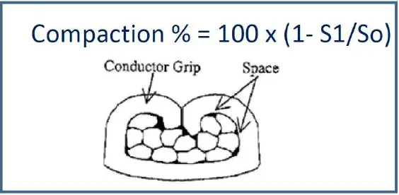
According to authoritative industry standard definitions and mass production experimental data verification, for an ideal terminal crimping state, its conductor compression ratio must be strictly limited within a narrow process window of 15% – 30% (the industry-recognized optimal starting point is usually between 15% and 20%).
When under-compressed (compression ratio < 15%): The copper wire is not fully compacted, leaving air gaps inside the wire harness. This causes the actual conductive contact area to sharply decrease, and contact resistance to spike. Under high-power energy storage, high-voltage equipment, or heavy-duty industrial control conditions, it easily forms a fatal "heat source", triggering terminal ablation or even equipment fires.
When over-compressed (compression ratio > 30%): Destructive excessive deformation occurs between the terminal and the copper wire. The cross-sectional area of the copper core is severely damaged, creating stress concentration. In a vibrational environment during long-term equipment operation, it easily induces metal fatigue fracture.
III. Why is relaxing to ±0.05 mm absolutely unacceptable?
Engineers new to the wire harness processing industry often question whether the ±0.03 mm requirement is too strict: "Can we relax the process to ±0.05 mm? This would lower the defect rate and extend the die life."
From the perspective of quality control in a wire harness factory, let's calculate an engineering equation. Suppose the standard crimp height for a high-precision electronic terminal is set at 1.20 mm:
If the tolerance is relaxed to ±0.05 mm, the actual height fluctuation range on the production line will drift to 1.15 mm – 1.25 mm.
For miniaturized, high-density modern connectors, this seemingly insignificant 0.05 mm deviation, projected onto the "conductor compression ratio" curve, is enough to let the crimp state drop straight out of the 15%-30% safe process window.
In other words, once the deviation exceeds 0.05 mm, the crimp point will inevitably face either **"loose internal pseudo-connection (under-compression)"** or **"physical damage to the copper core (over-compression)"**. Therefore, maintaining the ±0.03 mm baseline is by no means an overly demanding process requirement, but a tolerance limit that engineers in major factories must lock in to ensure that the compression ratio of every wire harness falls securely within the safe zone.
IV. The "Three System-Level Disasters" Caused by Crimp Height Deviation
If this ±0.03 mm baseline cannot be maintained in large-scale mass production, the equipment delivered to end-customers will face three fatal hidden dangers:
Severe degradation of electrical performance (abnormally amplified contact resistance)
A larger crimp height leads to residual gaps. In low-voltage signal harnesses (such as medical sensors, industrial buses), it will cause high-frequency signal loss or data error codes; in power harnesses, the abnormal temperature rise brought by high impedance is a major cause of equipment downtime and thermal runaway.Collapse of mechanical strength (pull force not up to standard)
A larger height prevents the terminal wings from fully wrapping and locking the wire. Under high-frequency movements of industrial robots, equipment dragging, or bumpy vehicle road conditions, the wire is extremely prone to being ripped right out of the terminal sleeve, leading to instantaneous power outages or core module failures.Overdraft of long-term reliability (hidden fatigue fracture)
This is the most troublesome "invisible killer" in after-sales service. If the crimp height is too small (over-stamping), the copper core sustains "internal injuries". Such defective products can often pass standard factory continuity tests and pull tests smoothly, but after 1-2 years of continuous equipment operation, the damaged copper wire continuously expands its micro-cracks under constant high-frequency micro-vibrations, eventually leading to a complete open-circuit paralysis.
V. The Moat of High-End Wire Harness Manufacturers: "Three-Dimensional Verification System"
As a professional high-quality wire harness manufacturer, the quality we promise our customers never just stays on paper. Truly mature custom wire harness factories deeply understand: Relying solely on a micrometer to measure crimp height is far from enough. Excellent terminal crimping is a comprehensive output of multiple process variables, including terminal material matching, wire structure analysis, automated wire stripping accuracy, and crimping die blade management.
To ensure yield and reliability, top wire harness enterprises in the industry have established a strict **"Three-Dimensional Verification System for Crimping Quality"**:
Crimp Height and Width Measurement (Online SPC Monitoring): The production line is comprehensively equipped with precision digital micrometers and Crimp Force Monitors (CFM) featuring CPK automatic statistical functions to achieve high-frequency spot checks and statistical process control during production, preventing systematic deviations.
Terminal Pull Force Testing (Destructive Mechanical Verification): High-precision tensile testing machines are used for destructive physical stretching to visually verify whether the mechanical bite strength of the metal connection exceeds the upper limit requirements of IPC or customer standards.
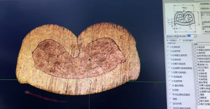
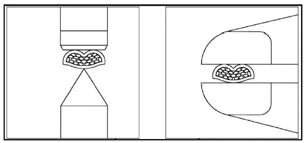
Cross-section Metallographic Analysis (The Ultimate Quality Criterion): This is a core verification item that senior quality auditors of major top-tier clients must check. By embedding the crimped terminal in resin, precision cutting, polishing, and acid etching, it is placed under a metallographic microscope and magnified (50x-200x) to visually analyze the internal **"conductor compression density"** and **"terminal roll morphology (symmetry, support surface burrs, bottom-out interference)"**. In the high-end wire harness manufacturing field, cross-sectional metallographic data is the ultimate truth that never lies.
VI. The system reliability of equipment essentially depends on the reliability of wire harness crimping
Outsiders often mistakenly believe that wire harness processing is a "labor-intensive" assembly without technical barriers, assuming that as long as the most expensive fully automatic crimping machines are purchased, qualified products will naturally be produced.
But in the eyes of senior wire harness process experts, first-class manufacturing quality is built on the team's profound insight into the underlying process: it is the rigorous micrometer-level management of crimping die blade wear, the ultimate pursuit of fully automatic wire cutting and stripping precision, and the closed-loop review of daily cross-section analysis data.
Never underestimate this tiny ±0.03 mm. Inside a high-end precision device (whether a smart car, an MRI machine, or a 6-axis industrial robot), there are hundreds or thousands of terminal crimp points intertwined. If even a single point fails because it falls out of tolerance, the most powerful master chip and the most precise mechanical structure may instantly paralyze completely due to a power loss or signal failure.
Revering industrial standards and sticking to the ±0.03 mm crimp tolerance is not only the process baseline for leading high-end wire harness manufacturing enterprises, but also the professional foundation of every wire harness engineer's commitment to product reliability.


